Basic Principles
Wind direction measurement accuracy is a critical factor affecting wind turbine production efficiency. When installing wind speed/direction sensors on turbines, the wind vane axis must coincide with or be parallel to the turbine's centerline according to the installation position. As shown in Figure 1, A1 and A2 represent wind vane axes parallel to the nacelle centerline. Better alignment between the wind vane axis and the nacelle centerline improves the turbine’s accuracy in facing the primary wind direction, thereby increasing production efficiency.
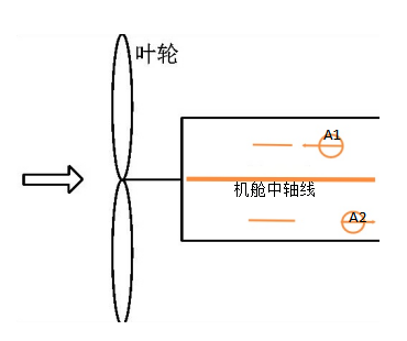
Figure 1: Sensor wind vane axis orientation parallel to centerline
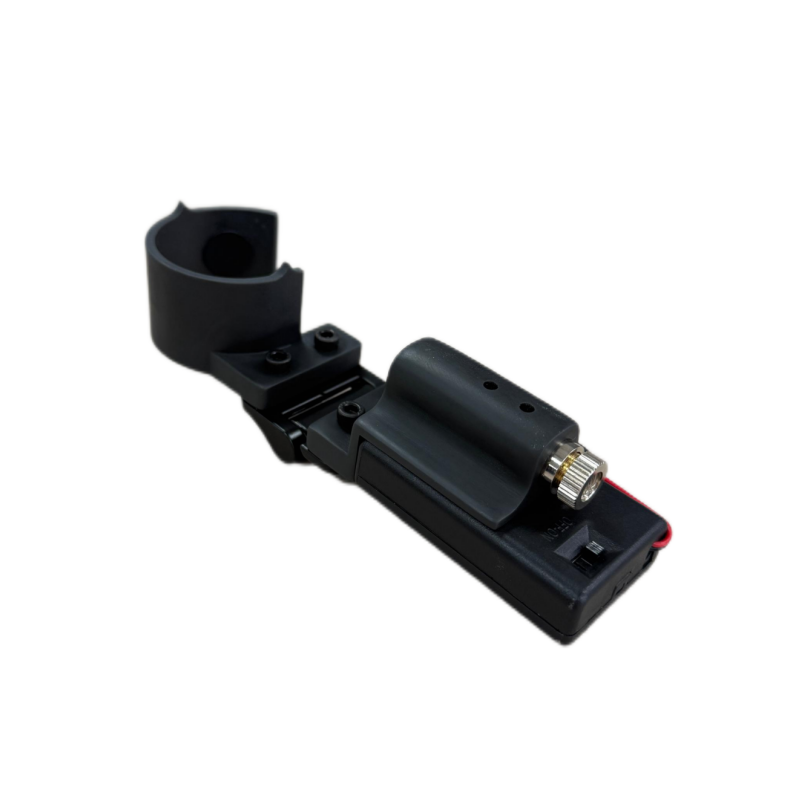
When the alignment tool’s pointer aligns with the sensor’s "N" direction, the laser crosshair moves strictly along the wind vane axis due to the hinge’s bending angle. Thus, aligning the laser’s vertical line with the centerline (or its parallel) at the installation point ensures parallelism between the wind vane axis and the centerline.
Alignment Tool Usage Steps and Methods
1. Determine Turbine Centerline & Parallel Line Through Sensor Position
Identify the turbine’s centerline or a parallel reference line on the nacelle.
Based on the sensor’s installation point, mark a line passing through it that coincides with or runs parallel to the centerline. Label this position for subsequent laser crosshair alignment.
2. Finalize Sensor Orientation Using Alignment Tool
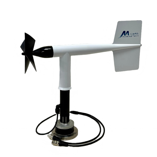
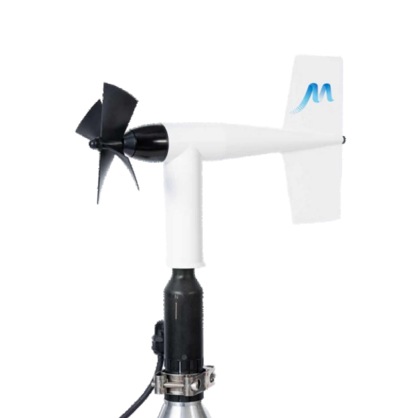
Install the sensor and pre-tighten the clamp without securing it fully. Orient the "N" direction toward the rotor hub or tail (varies by turbine model) per main controller requirements. Attach the tool above the sensor mast’s cable outlet (Figure 2). Align the tool’s pointer with "N": If "N" faces the tail: Align distal pointerwith "N" (Figure 3). If "N" faces the hub: Align proximal pointer with "N" (Figure 4). Activate the laser an dsimultaneously rotate the sensor mast and alignment tool. Tighten the clamp** once the laser crosshair aligns with the mark from Step 1. The wind vane axis now runs parallel to the centerline.
![]()
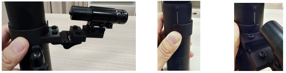
Figure 2: Alignment tool positioned above cable outlet Figure 3: Distal pointer alignment Figure 4: Proximal pointer alignment

WeChat QR code

Online Service
Copyright © 2018-2025 Qingdao Maritech Technology Co., Ltd. Record No:鲁ICP备2023007181号
technical support:WDL